Erosion Control
Water management controls
Pipe drop structures and flumes
What, Why, When and issues to look out for
What
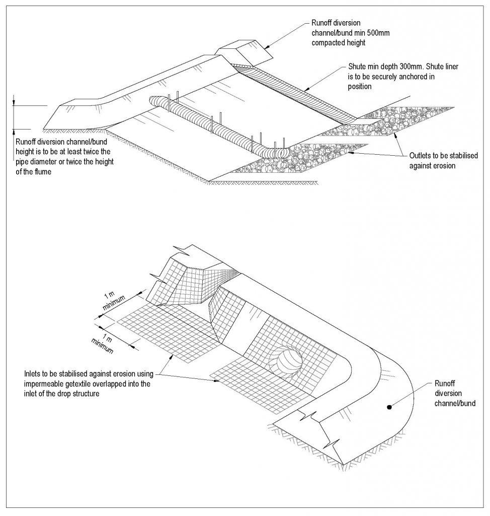
A pipe drop structure or flume is a temporary pipe structure or constructed flume placed from the top of a slope to the bottom of a slope.
Temporary pipe drop structures or flumes can be made from needle-punched geotextile fabric, concrete, steel or plastic half-round pipes, rock, sandbags, lay-flat or construction ply. You can use any product that conveys water safely over exposed soils or unstable slopes.
By ‘temporary’ in this case, we mean short to medium term. If the use might extend for longer, then you should use other tools.
-
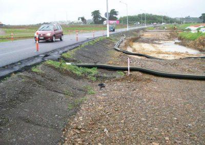
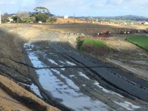
Flume conveying clean water over the works area (Source: SouthernSkies).
-
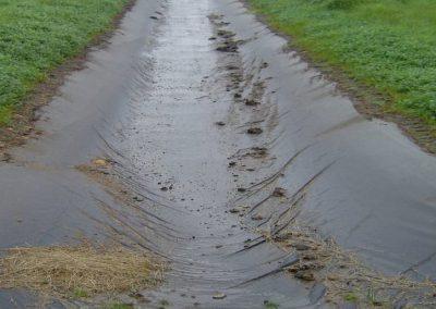
Geotextile-lined flume.
-
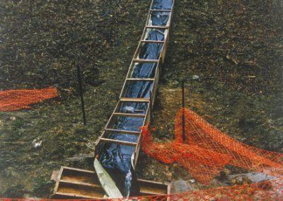
Wooden flume lined with impervious material.
Why
The device conveys a concentrated flow of either clean or dirty surface runoff down a slope, without causing erosion.
When
Use pipe drop structures or flumes when you need to convey concentrated flow of surface runoff down a slope steeper than 3:1 (H:V).
They can be used as follows:
- Both devices are commonly used with diversion channels or bunds, which collect and direct surface runoff into the structure
- Both devices can be used to divert flows down batters to the forebay of a sediment retention pond and also at the final point of discharge into the receiving environment
- You can also use flumes to stabilise an actively eroding gully head.
Issues to look out for
Pipe drop structures and flumes have the following limitations:
- If the drains fail by overtopping, piping or pipe separation, there may be severe erosion
- Pipe drop structures are suitable up to a maximum catchment of 1 ha before specific engineering design is required
- Flumes may be used with contributing catchments of up to 5 ha (subject to the relevant design essentials)
- If the foundation material is unstable, there can be slippage or slumping and damage to the devices
- The flume’s outlet must be stabilised to avoid mobilising more sediment through scour
- You will need to monitor and maintain regularly to make sure that the structures are working.
Design essentials
For both pipe drop structures and flumes, the following points are design essentials for the tool to work:
- Always use them when slopes are steeper than 3:1 and when channelised surface runoff must be conveyed down the slopes.
- They must be impervious to prevent water from flowing under the structure. Spray-on copolymer is best. If using a needle-punched geotextile, use two layers to minimise erosion.
- The height of the runoff diversion channel or bund that diverts flows to the pipe or flume (when measured from the invert) must be at least twice the pipe diameter or twice the flume height.
- The inlet to the flume or pipe should include a 1 m stabilised entry apron to minimise drawdown scour, eg by using geotextiles. This needs to be on at least a 3% grade.
- Extend the devices beyond the toe of the slope you are protecting. Protect the outfall with an energy dissipation device (eg geotextile, sand bags, rip-rap).
For pipe drop structures, the following points are also design essentials for the tool to work:
-
Table 6 shows the maximum catchment area draining into a pipe drop structure. For catchments larger than 1 ha, specific engineering design will be required.
Table 6: Sizing criteria for pipe drop structures Pipe diameter Maximum catchment area 150mm 0.05ha 300mm 0.20ha 450mm 0.60ha 600mm 1.00ha Specific design required >1.00ha - The pipe drop structure should have:
- A gradient no shallower than 3:1
- An inlet bank (made of compacted material) or wing walls at the inlet of the pipe that are at least twice the height of the pipe drop structure
- Adequate provision for securing the pipe drop structure to the slope. Anchor the pipe drop structure at least every 4 m.
For flumes, the following points are also design essentials for the tool to work:
- Limit temporary flumes to the catchment areas shown in Table 7:
| Catchment slope | Maximum catchment area |
|---|---|
| >18% | 2.5ha |
| <18% | 5.0ha |
- When contributing catchments are greater than these thresholds, specific engineering design is needed.
- The temporary flumes must provide:
- An effective flume width of 1.5 m per ha of contributing catchment area. (Note: ‘Effective flume width’ is approximately the surface width of shallow flow in the flume, which will be slightly larger than the flume base width).
- A gradient that is no shallower than 3:1.
- At least twice the flume’s height of compacted material of inlet bank or wing walls at the top of the flume.
- At least a 300mm deep cut-off trench at the top of the flume, to avoid undercutting the fabric.
- At least a 300mm flume sidewall height (or flume depth).
- Geotextiles have maximum flow rate limitations; check your plans with the manufacturer.
Construction and operation
When constructing and operating pipe drop structures
Their main cause of failure is for water to saturate the soil and seep along the pipe where it connects to the runoff diversion channel. To make sure this doesn’t happen:
- Backfill and compact properly around and under the pipe, with stable material, to achieve firm contact between the pipe and the soil at all points
- Use pipe material that is either rigid or flexible depending on the needs of your site, eg if vehicles cross an area where a flume passes, use flexible pipe
- Pin or secure the structure to the slope in the required position at least every 4 m. Use at least two anchors equally spaced along the length of the pipe
- Make sure that all pipe connections are watertight.
When constructing and operating flumes
Their main cause of failure is for the entrance to be outflanked or the invert of the flume to be scoured. To make sure this doesn’t happen:
- Waterproof the entrance of the flume by trenching in an appropriate impervious geotextile or plastic liner, to channel all flows directly into the flume.
- Orientate flumes directly downslope.
- Wherever practical, construct the flume on well compacted soils or undisturbed soils.
- Make sure that the bund or wing walls are high enough and shaped appropriately to direct water to the centre of the flume.
- Use compacted earth, sandbags or other measures so that water doesn’t flow past the entry.
- Provide a stabilised apron 1 m wide at the top of the flume (eg geotextile fabric), to minimise drawdown scour as water accelerates down the flume.
- Make sure that the flume is deep enough to contain water.
- Work to a minimum 300 mm depth.
- Support timber or other rigid construction flumes well enough so that movement and settlement don’t separate the joints.
- Securely fasten two layers of fabric to the soil. Follow the manufacturer’s specifications, or pin the fabric at 0.5 m intervals.
- Provide a velocity dissipation structure at the bottom of the flume, eg sand bags or loose rock. Don’t discharge water directly onto bare, unstable or erodible soils.
Maintenance and decommissioning
When maintaining pipe drop structures and flumes
- Inspect the devices weekly and after each rain event, and do any maintenance required immediately.
- Keep the inlet open at all times.
- Check for evidence of water bypassing, undermining or overtopping the device.
- Check for scour at the base of the device or in the receiving downstream area. If eroded, repair the damage and install additional energy dissipation measures.
- If there is downstream scouring, implement other preventative measures or reduce the flows discharged into the device.
- Modify and extend the length of the device as earthworks progress.
- Keep the device in place until runoff has been controlled and all disturbed areas are stabilised, or until permanent stormwater systems have been commissioned.
- Make sure that the devices do not cause ponding onto inappropriate areas (eg active traffic lanes, material storage areas, etc).
When decommissioning pipe drop structures and flumes
- Keep the devices in place until runoff has been controlled and all disturbed areas have been stabilised, or until permanent stormwater systems have been installed and commissioned.
- Remove temporary pipe drop structure and flume materials and, where possible, re-use and recycle.
- Stabilise all the areas that were disturbed as part of the removal process. Apply seed and fertiliser and/or protect the surface with mulch or erosion control blankets.
